Helicopter Control Systems – ECE 6552

For the Georgia Institute of Technology and its Nonlinear Systems class, my group performed analysis on a model for a small coaxial RC helicopter. The objectives of our study were to:

  • Construct a model that accurately represented the dynamics of our system.
  • Stabilize the system by finding and utilizing a Lyapunov function and feedback linearization.
  • Create a simplified linear control system derived from the nonlinear dynamics of the model; then implement this control system on a real, commercially available RC helicopter.
The original RC helicopter.
Fig. 1. The original RC helicopter.

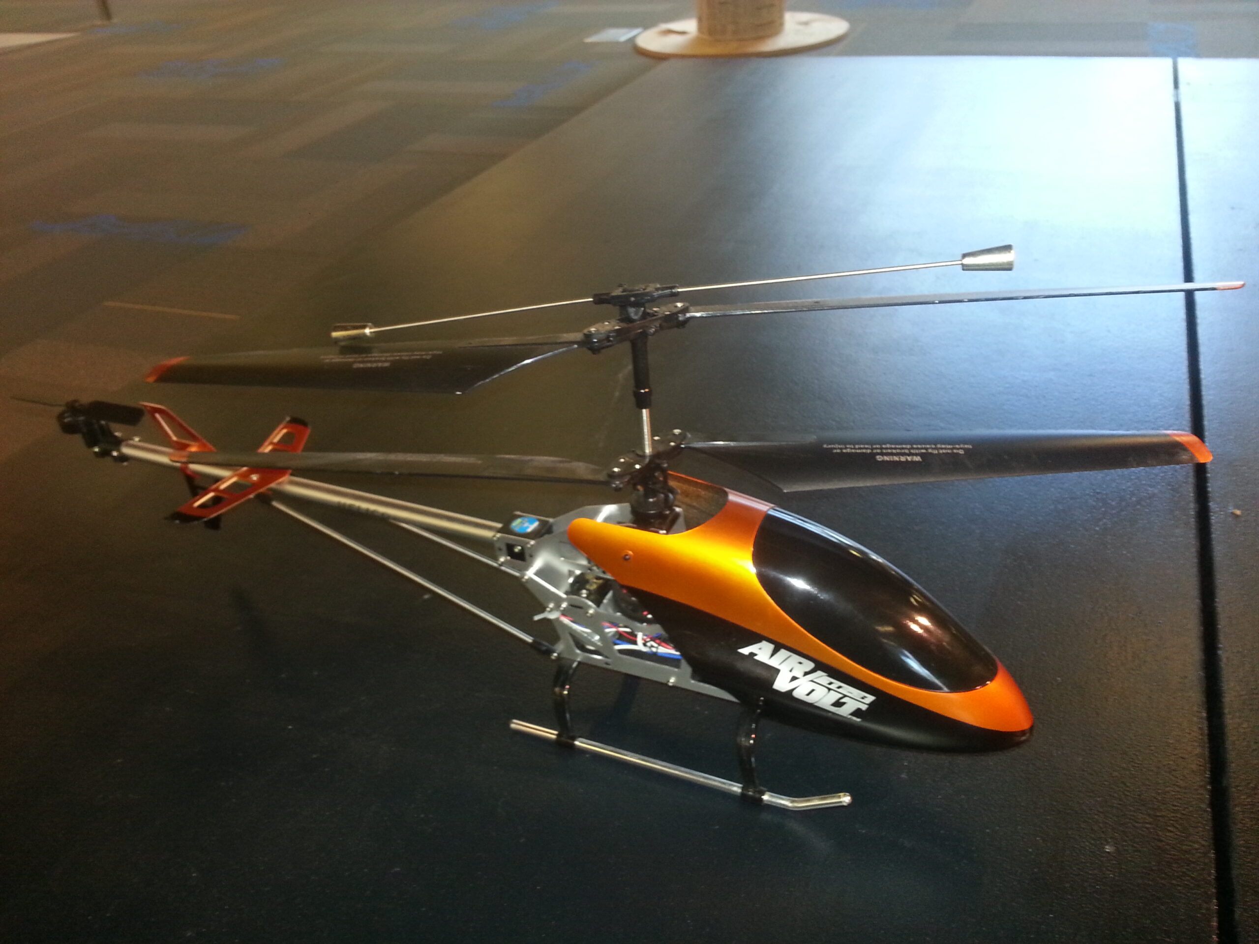
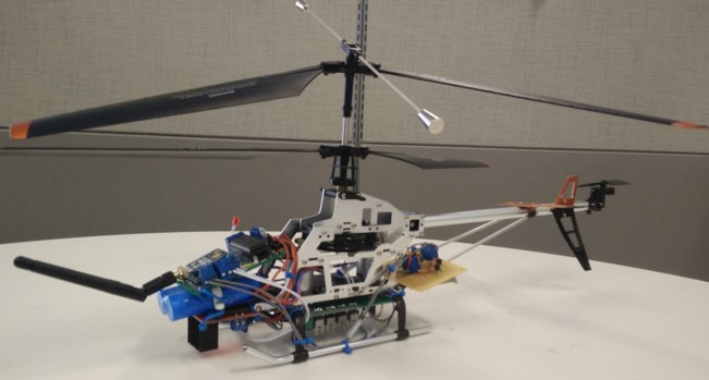
A standard RC helicopter with a burnt out controller was chosen as a starting point. A microcontroller (ARM Cortex M-0) was chosen to be the brain of the system. A LSM9DS0 IMU was chosen to be the acceleration and rotational sensor. The reference commands are to be transmitted wirelessly to the system by an XBee-PRO® 900HP transmitter.

The main rotors are powered by two motors which are to spin counter to each other. This is the central idea to the operation of coaxial helicopters. As a rotor rotates a torque is induced on the body of the helicopter which would cause the body to begin rotating. Since the rotors are spinning in opposite directions, their torque cancels out. By varying the difference in speed of the rotors, a small amount of torque can be allowed to cause desired rotation of the helicopter’s body.

The starting point of model development was based upon the work by D. Schafroth et al, titled “Modeling, system identification and robust control of a coaxial micro helicopter”. From there we developed the model, shown in Fig 1., to describe our system.

Fig. 2. The state variables and systems of equations describing the coaxial helicopter.

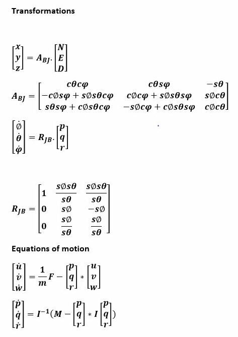
Here x,y,z and ϕ,θ,ψ are the position and the angular positions of the center of mass of the helicopter with respect to the origin. u, v, w and p,q,r are the linear and angular velocities in the x,y, and z directions. Ωdw and Ωup are the rotor speeds. In our model we assume the motor inputs to be equal.

The objective of the controller is to stabilize the helicopter in hover to a desired z value. During hover the system has freedom of angular velocity and acceleration about the z axis, or yaw.

The final step was to prepare our helicopter to perform our real world experiment. We converted our mathematical control system into a discrete version to run in our helicopter’s controller. The biggest problem we ran into was the weight of our new controller. The helicopter was only able to maintain flight for a few moments before succumbing to the weight and drifting downward. However for a few moments we where able to achieve a stable hover, and our control system performed quite well.

Fig. 3. The finished RC helicopter with a custom controller.

With more time and a larger budget, there are many things we could have done to improve the performance of our experiment. A more powerful helicopter with a longer lasting battery would have eliminated the weight issue and enabled us to perform longer tests. In the end we successfully confirmed our mathematical model with real world experimentation.

Presentation Materials

Click here to download our PowerPoint presentation.

Forestry Worker Safety Project

In conjunction with the Georgia Institute of Technology, as a final end of program (graduation) project, my team designed and prototyped a worker safety device for forestry workers. It incorporates a lot of cool devices and modules like a powerful GPS and Radio as well allows in socket programming of the microcontroller. See more at the link below!

http://ottaviano.me/forestry_project.html

Crazy Blooms

I know that this post is not consistent with the topic of my blog; however with gardening to be one of my relaxing hobbies, I am inclined to share it here. Gardening has been something I do in my spare time for the past 2-3 years of my life. Nothing extreme but I would usually grow whatever could fit on my cramped apartment porch.

Now while this post isn’t directly related to my usual technology centric posts, I am actually in the process of designing and building a programmable LED plant grow system! The details of which will of course appear here when it’s time. Here are some little tidbits of my upcoming project…

  • Between 120-200 w power output.
  • Microcontroller day/night programmable.
  • 40-70 3 Watt Leds!

I am currently still waiting on parts to come in but I plan to start the build within the next month so keep posted.

I currently have lemon and orange trees indoors during the cold summer here in Georgia. These trees are fairly young with the lemon tree being three years old and the orange tree being only two. But at such a young age, they wouldn’t be able to survive any kind of real deep freeze without serious damage. I did, however, leave them outside a few too many chilly nights before bringing them indoors. To my surprise, I think they have decided among themselves that is now spring and time to flower! I am excited to see what size crop they will yield.

Bluetooth LE Struggles

So I have been working pretty hard lately trying to get this whole Bluetooth LE thing to work. I am using the adafruit Bluetooth LE board to prototype this thing. As is shown by the obvious silk screen on the board this thing is based on the Nordic nRF8001 Bluetooth chip. Datasheet here: nRF8001_PS_v1.3

The Nordic pin-out is logically connected to the board’s pin-out so there aren’t many surprises here. I have it hooked up to an mbed chip for testing and after some annoying work around involving the bit order of SPI transfer and the mbed being unable to change the mode, (Grrrr), I have both chips talking happily.

0725151227

The real work, unknown to me at first, was in configuring the service pipes. At this point I have the chip successfully announcing itself to the Bluetooth universe!

ble capture

However upon connecting with a peer device I get an instant error connecting message on the peer device and this output to my serial console.

blue capture 2

These messages basically say:

  1. A connection has been established with a peer device.
  2. A new service pipe has been opened.
  3. A disconnect event with the message “Remote device failed to complete a Security Manager procedure”.

How frustrating. After ravaging the internet to figure out what this “Security Manager Procedure” is, when it should be operating in an unauthenticated bonded relationship, I fail to find a solution to this issue. Even using the setup data from adafruit’s demo code I still get this error. At this point it must be something I am just not understanding with the nRFgo Studio software and the whole idea of GATT services.

Scrutinize my code here at the mbed site. If you figure something I have missed let me know! But anyways…

…back to work I guess.

MATLAB and the Raspberry PI (An old document I dug up)

I wrote this document last year for a communications project and just found it while rummaging through some old files. Maybe it will be of use to some of you interested in advanced debugging of Raspberry Pi applications. You can take a look by clicking the link below.

MATLAB_RPIE.pdf

An introduction from the document:

The purpose of this document is to describe the methods and benefits of using MATLAB and Simulink to analyze the physical inputs and outputs of the Raspberry Pi computer. This document is written at the level of a user who is familiar with basic electrical concepts but no exhaustive circuit’s knowledge is required. The reader should also be familiar with Linux and the Raspberry Pi.

In this guide python will be used as the scripting language since it is most commonly used for Raspberry Pi programming. Advanced knowledge of python is not required to understand this guide. A Raspbian Linux image provided by MATLAB for the Raspberry Pi will also be used. Installation and configuration is demoed under MATLAB R2013a but is similar for most versions and will be covered first.